Fig9 Side view of the Lebaron in front of the garage doors.
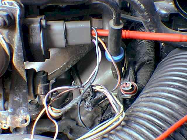
Fig3 View shows back probing the TPS signal wire (OR/DB) at the TPS
connector.
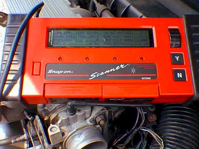
Fig7 View of datastream on the Snap-On Scanner while TPS is displaying
4.98 Volts.
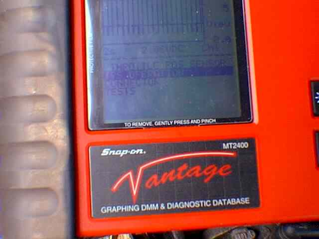
Fig4 View of the Snap-On Vantage in graphing mode while back probing
the TPS signal wire (OR/DB). Notice the 60 Volt spikes.
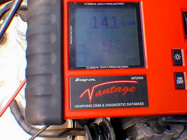
Fig6 View of the Snap-On Vantage displaying battery voltage and 60
volt spikes on min/max while back probing the TPS signal wire.
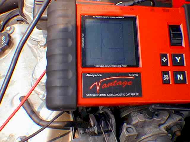
Fig5 View of Snap-On Vantage displaying injector wave form while probing
the exposed area of the Injector #1 control wire (WT/DB).
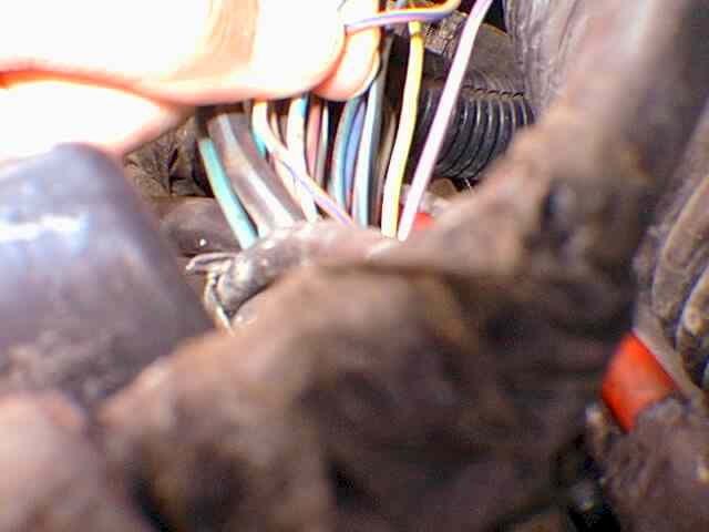
Fig. 1 View of TPS signal wire (OR/DB) and Injector #1 control wire
(WT/DB) both chafed in the same area. These wires were intermittently touching
one another in the wiring harness.
|
92 Chrysler Lebaron 2dr Convertible
3.0 Liter 4sp/AT
58,883 miles
Intermittent MIL light & intermittently runs poorly
SYMPTOMS
Recently a regular customer dropped off her 92
Lebaron ragtop with an intermittent problem. The customer reported that sometimes,
while driving, she would notice that the engine would seem to stumble and
run poorly and sometimes the MIL light would illuminate. The customer also
stated that engine temperature did not seem to matter and the problem would
come and go, and last for varying time intervals. Our initial road test
revealed a well running car with no problems. "Typical darn intermittent"
we thought.
VEHICLE OVERVIEW
Our subject vehicle is equipped with the popular drivetrain
package of 3.0 Liter, OHC engine and the Ultradrive A-604 transaxle. Engine
functions are controlled by the Powertrain Control module or PCM. An optical
ignition pickup provides two reference signals, one for cylinder ID and one
for crankshaft position, for fuel and spark delivery. A manifold absolute
pressure (MAP) sensor is used to calculate engine load instead of any type
of air flow meter. The PCM also controls the auto shutdown and fuel pump relays
to power the fuel pump, ignition coil, injectors, and oxygen sensor heater.
Besides controlling engine functions the PCM monitors and controls charging
system voltage. To aid in diagnoses the PCM also has a reset counter that
keeps track of how many ignition cycles have occurred since the last fault
code was set or battery disconnect.
Transmission functions are controlled by the Electronic Automatic
Transaxle Controller or EATX. The four speed transaxle is a fully adaptive,
electronically controlled transmission that uses feedback sensors to adjust
functions and monitor performance. With a good scan tool the EATX can supply
a wealth of diagnostic information on transaxle condition, history and current
sensor values. These computers and others are connected together by a serial
data network called the Chrysler Collision Detection System or CCD bus.
Each computer module uses this network to communicate and exchange data
with other modules in the vehicle.
THE DIAGNOSTIC
Studying the Technical Service Bulletin titles took
about ten minutes but did not reveal any similar symptoms. We called the
customer to obtain authorization for a "Level 1 Diagnostic". In short order,
a Level 1 Diagnostic at our shop is a package consisting of labor and various
tool fees, normally consisting of: 1) Visual Underhood Inspection
(VUI). 2) two hours labor. 3) Scan Tool connect and code interpretation
fee. 4) Datastream Analysis. 5) Information Access Fee (TSB & procedures
search) and, if used, 6) software fee for the Snap-On Vantage Graphing Multimeter.
After obtaining authorization we began our visual underhood inspection. A
visual inspection of all underhood equipment did not reveal anything out
of the ordinary. It was time to connect the scan tool. We found two codes
present in memory. Code 21- O2 Sensor not switching and Code 24-Throttle
Position Voltage too high. With the car running hot, the O2 sensor seemed
to switch normally from 200 to 800 millivolts. The TPS at idle was. .96V
and ok. Studying the rest of the datastream values did not reveal any abnormalities.
We decided to clear codes and road test again. Once again the car ran very
well. So well that on the test drive I wondered how much time technicians
all over the country spend test driving cars in hopes that the car will become
symptomatic.
RESULT TIME
In lieu of the fact that the car was running so well and that
no codes had returned, we decided to park the car for the day. The next
day we started the car again. This time the engine seemed to be stumbling
at first, then it would clear up and go to a higher than normal idle. Often
Chrysler vehicles will be symptomatic only for a moment when started if
there is a hard fault, because the PCM quickly supplies a substitute value
to replace the failed sensors value. A view of the datastream now revealed
some interesting information. Code 24 for high TPS was set again and the
TPS value in the data stream showed 5.00 V (fig. 7). While the car was symptomatic,
we checked the 3 TPS wires with the Vantage in the voltmeter mode. A check
of the TPS feed wire (VT/WT) revealed a normal 5.00 V reference. Testing
the TPS ground wire (BK/LB) revealed a good ground reading at 0.02 V. However,
when testing the TPS signal wire (OR/DB) we found 13.5 V (fig. 3). Now this
did not agree with the current 5 V reading on the scan tool. We believe that
the scan tool software or the vehicles computer can not display any voltage
over 5 V to the scan tool. This is probably limited since there should never
be more than 5 V on this circuit normally.
TWO THEORIES
Anyway, the voltmeter showed 13.5 V so we knew this
was the true reading. But how can 13.5 V be present on this wire? Even if
the TPS is shorted internally the maximum voltage available on this circuit
is only 5.00 V. Vantage was also capturing min/max voltage values on this
circuit. We noticed voltage was maxing at 60.00 V (fig. 6 & 4). How
could this be? We turned the engine off and left the key on. With KOEO we
noticed that the problem was gone and TPS came back to the normal .96 V.
After some pondering and discussion, we had developed two theories that
we wanted to test. Theory 1) The TPS signal wire is touching a wire that
carries battery voltage with the engine running. (Although this would not
explain the 60.00 V max readings.) Theory 2) The vehicles onboard computer
has been compromised internally in which the computer, in error, is sending
voltage out the TPS signal wire. This would have to be some internal short
or catastrophic failure since the computer should only be sampling voltage
at this pin and not supplying voltage there.
To test the first theory we decided
to let the car run again while tugging on the various underhood wiring
looms. While tugging on the main computer harness near the battery, we noticed
the TPS reading would drop to normal and the car would idle down (fig 10
& 11). More tugging created the high idle and high voltage readings
again. We were somewhat confident that the TPS signal wire was touching another
wire somewhere in the cars intestines of wiring. Now came the moment of truth.
Should we run a new TPS signal wire between the TPS and the computer and
be done with it, or should we just go a little further? Well, to quote Mitch
Schneider, "The deeper you go the more you know".
WIRING INSPECTION
Since the wiring was a fairly short run from the TPS
to the computer in the L/F fender, we decided to open the wiring loom. Beginning
at the TPS connector we pulled out the TPS signal wire (OR/DB) about twenty
inches from the connector. Not far from a junction where two wiring harnesses
meet, we found our gremlin. With the wiring loom open and the TPS signal
wire out for careful feeling and visual inspection we found a small section
of wire exposed (fig. 1, 2,8). The wire's insulation appeared to have been
crushed at one time. Only one other wire exhibited the same crushed-exposed
symptoms. That wire's color was (WT/DB). With the car running, this
wire showed the 13.5 Volts and the 60 Volt spikes. When testing this wire
with the Vantage in the waveform mode, look at what we saw (fig. 5). Look
familiar? After studying the wiring schematic we found this (WT/DB) wire
to be the Injector # 1 control wire. Since this wire was touching the TPS
signal wire, this explained the 60 volt spikes we were seeing.
After repairing both wires and taping
up the wiring harness, we cleared the TPS code and road tested the car one
final time.
As to the O2 sensor code, it never
reset and the O2 sensor activity appeared normal so we advised the customer
that there was no evidence a repair was necessary at this time for the O2
sensor. Most likely the temporary loss of fuel mixture control caused this
code to set.
One of the nice things about this
business is that it is never dull. You may see the same type of vehicle
or symptom, but that doesn't mean it will be the same old problem. Who would
of thought we would see an injector waveform riding on a TPS circuit.
Mark Giammalvo MAT, SAE
Glenn Giammalvo MAT, L1
 Glenn & Mark

|