Return To The Motor Age Articles Index Page....  
 July 1998 By Glenn & Mark Giammalvo


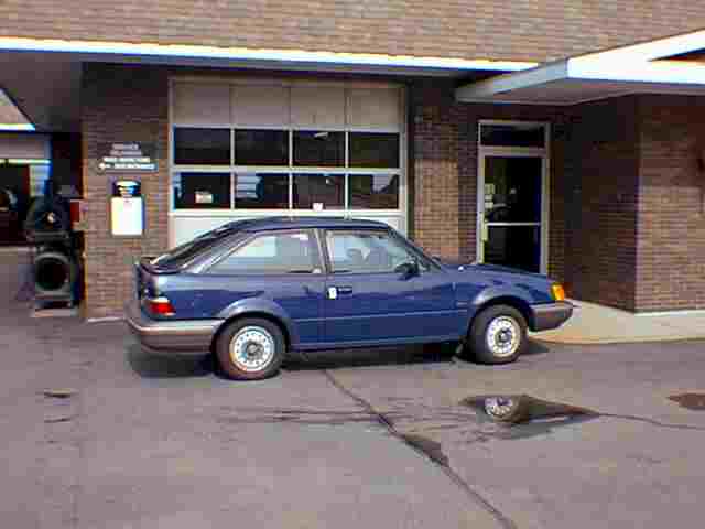
With this 90 Ford Escort, the question was, "who's fooling who?" We finally found the fibbing component. 


 Here we see the MAP sensor displaying 158 Hz at WOT. Hmm... the MAP is reporting full load yet the car was still running lean. 


 Here we are using the Snap-On Vantage to view the CTS reading over the ACT. Using a meter with dual displays like this is a time saver as you can verify more than one reading at a time. 


This is a side view of the idle control motor or "DC Motor" The idle tracking switch is  built into the motor and senses when the motors shaft touches the throttle lever. 


  Here is what we recorded from the TPS switch on a throttle sweep. Not exactly a healthy sensor. We believe this faulty sensor caused the PCM to set the MAP code. 


90 Ford Escort 3dr 
1.9 Liter 5sp/MT 
103,741 miles 
Bucks heavily under moderate to full acceleration accompanied by a blinking MIL lamp. 

Anyone who repairs today's modern vehicles will surely agree that automotive driveability diagnostics can be both challenging and aggravating but usually for us technicians it's a labor of love. This time the vehicle in the shop was a 90 Ford Escort. The vehicle is owned by one of our employees who works at our shop as an automobile reconditioner & detailer. The employee was complaining that suddenly the Escort would buck violently when accelerated moderately and that during the bucking the check engine lamp would flicker on and off. 
 

System Overview 

  Our Escort's Powertrain Control Module (PCM) operates a central fuel injector (CFI) and Fords well known Thick Film Integrated (TFI) ignition system, to control fuel and spark delivery. A Manifold Absolute Pressure (MAP) sensor and an Air Charge Temperature (ACT) sensor are used to monitor engine air requirements and a Throttle Position Sensor (TPS) is used to report throttle position. A Coolant Temperature Sensor (CTS) is used to determine engine temperature and a heated O2 sensor is used to control fuel trim. Onboard diagnostics is limited to a self test function that lists and stores three types of trouble codes. Key on/engine off (KOEO) codes, key on/engine running (KOER) codes, and continuous memory codes. 


Test Drive 
At first we noticed the car hunted up and down for idle speed. When discussing this with the owner he reported that he had been driving the car with the hunting idle problem for quite some time and that someone had told him that a new idle control motor would correct that problem. Since the hunting idle didn't bother him he asked us to ignore that and concentrate on the bucking problem. A short test drive confirmed the bucking. The vehicle actually drove quite normally if the throttle was applied slowly. However, if you applied moderate to heave throttle, the car would buck wildly. The engine seemed to accelerate normally when raced up, no load, with the shifter in neutral. 


Testing Time 
After a brief check of powertrain service bulletins we began our diagnostic with the visual underhood inspection but it did not reveal anything unusual. The bucking seemed consistent with what might be a lack of fuel so we road tested the car while monitoring fuel pressure. While the car was bucking we had good fuel pressure at 15 PSI. We connected our scan tool and pulled the following KOEO codes: 
13 DC motor not moving 
38 Idle tracking switch 
58 Idle tracking switch 
KOER codes pulled were: 
13 DC motor not moving 


Owner Consultation 
At this time our employee came over into the repair stall to see if we had any new information. We advised him that the only codes listed were for the idle control motor. That was not surprising news to him since he had been driving the car for so long with the faulty idle motor. Once again our employee reminded us that he did not mind the idle motor problem but really wanted us to get to the bottom of the bucking. As Murphy's Law would dictate; "The toughest driveability problems will occur on vehicles without datastream access."  Since this vehicle was not new enough for datastream access we decided to hook up our lab scope to the CFI unit to monitor the PCM's pulse width command of the injector during the bucking condition. When we applied moderate throttle on the road test the pulse width would reduce and the car would buck. For some reason the PCM was subtracting fuel while we were accelerating. Since the TPS and MAP sensors are the primary fuel control inputs on this model we decided to road test while monitoring them. On the first road test we monitored both the TPS signal wire, (DG/LG), and the MAP signal wire, (LG/BK). When the car was bucking we observed a good TPS signature showing correct throttle position. The TPS value was also acceptable at idle at .96V. With our DVOM set on Hz and connected to the MAP sensor's (LG/BK), wire we recorded 158 Hz at WOT when the car was bucking. This reading is consistent with the 0 in. of vacuum at WOT and the fact that we are geographically close to sea level. Looks like the MAP sensor is doing its job. The MAP sensor is reporting 0 inches of vacuum or, "full load", yet the PCM is reducing injector pulse width. Our next test found us with the Snap-On Vantage in dual voltmeter mode while simultaneously monitoring the CTS and ACT sensor. We found .56V on the CTS, (LG/YL), wire indicating a normal engine temperature of about 205F. On the ACT, (LG/PUR), wire we recorded 0.77V which corresponds to a normal intake air temperature of 175F with the car sitting 10 minutes after a hot soak. A little tip here: As soon as the car is started after a hot soak, ACT voltage should rise as the sensor reports the colder air entering the intake. What other fuel altering input could cause the PCM to still subtract fuel? We decided to road test one more time with the volt meter monitoring the 02 sensor wire, (DG/PUR). (All this work sure would have been a whole lot easier with a datastream and a dyno, frankly we were getting tired of driving this car). When the car bucked the 02 sensor reported lean. No surprise there, we sure know it's lean. The question is: Why? So far we know that all sensors are reporting correctly yet under a load the PCM cuts back fuel delivery to the CFI unit. Must be a faulty PCM right? Time to double check our data findings with the tec-line. 


Secrets 

We all know how secretive the manufactures are about computer strategy. Ever notice that there's always someone out there in our industry that has that little piece of "secret strategy" information that you could use? Today it was the tec-line specialist that was telling secrets. As soon as we gave him our sensor data and explained the "mysterious" lean command, Jerry, our Ford Specialist at Diagnostic Hotline, was pretty sure he knew the solution. Alas! We had been chasing a wild goose! Jerry stated that a new idle control motor would cure our bucking problem. We really didn't believe it at first. How can an idle control motor cause a bucking problem? We've replaced these idle control motors before for the "hunting idle" problem but we've never 
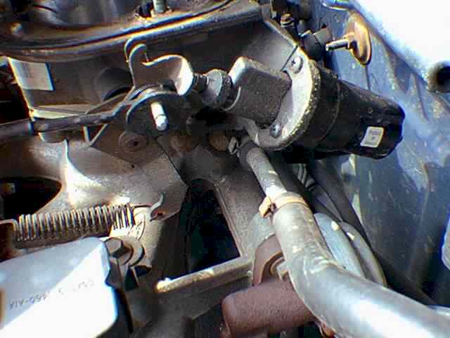
had one cause a driveability problem.  For those of you who don't know, the idle control motor used on this model is fairly common. It is simply a reversible motor that moves an idle control shaft out to push against the throttle lever to raise idle. When the PCM reverses the motor power and ground the control shaft is retracted therefore reducing the idle speed. In addition, the motor incorporates an "idle tracking switch" or " nose switch". Basically the idle motor has an internal switch that senses when the throttle lever is resting on the motors shaft. When the throttle is closed the throttle lever pushes against the idle motors control shaft. Inside the motor this moves a switch which sends about 10.5 Volts down the motors LG/W wire to the PCM. When the PCM sees voltage here it knows the car is at idle. When the throttle is pressed, the switch opens and the PCM sees 0V on the LG/W wire indicating throttle not closed. Well, we know this information and still fail to see how this relates to our problem. Listen carefully.....here comes the secret. Jerry went on to explain that when the PCM sees voltage on the LG/W wire, it assumes the car is at idle, and alters the fuel delivery program and goes to "lean idle strategy mode".  Basically, Jerry was telling us that the idle switch is probably stuck in the idle position at all times. In essence the idle switch is lying to the PCM telling it that: "were at idle...go to lean idle strategy." The vehicle is not designed to be driven when the car is running on the "lean idle strategy" in the first place. That's what happens when the idle switch lies to the PCM. That explains the lean  injector command regardless of all the sensors that were reporting a load. The PCM in effect ignores all other sensors when the idle control switch is reporting closed throttle. We confirmed 10.5 Volts at all times on the LG/W wire as Jerry had suspected and advised our employee that we would have to replace his idle control motor after all. 


Shame On You 
It's a shame that the automotive manufacturers don't publish more information like this regarding PCM strategy. It would make our job as technicians a lot easier and save the motoring public time and money in that with this "secret" information we could fix cars a whole lot quicker. There are some cases when the technician or shop is at fault for the cost of a long diagnosis because the information is available and they do not have the right tools or information. However in cases of "secret strategy" like this it is the manufactures who control the lack of release of proprietary information. And the lack of this information can only hinder our diagnostic process, and quite frankly, it's not the technicians fault. When asking Jerry how he learned of the "secret strategy" he mentioned he found out about it by heavy questioning of a Ford Service Engineer that he knew. Jerry had come across this perplexing problem a few times when he worked at a Ford dealer and was trying to figure out why the car's acted the way they did. Jerry had an interesting comment about manufactures and their lack of discussing strategy;  "When I worked for the dealer the manufacturers would send us to great training classes. They would even explain the composition of the metal that holds the MAP sensor, but as far as strategy and how the PCM will react to certain inputs, they just don't discuss that type of information." Maybe some day in the future the secrets will stop. But until then, keep your test equipment close at hand. 

Back Again 

About three months after this repair, the Escort was back in the shop again. This time our employee was complaining of an intermittent hesitation on acceleration. We were only able to duplicate the condition once. We wondered 
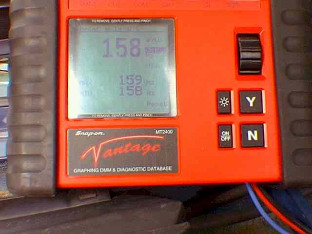
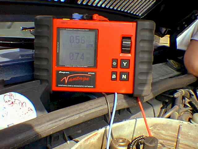
what demons possessed this car now. The car had code 22 set KOEO indicating MAP sensor out of range. A quick test with the DVOM on Hz showed 159 Hz KOEO 
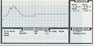
and 108 Hz at idle. A test of the MAP sensor's wave form on the Fluke 97 also revealed a healthy sensor. Now what? On a hunch we moved the lab scope over to the TPS signal wire. Bingo! Sometimes, during the throttle sweep, the TPS would drop low while the throttle was actually 70% to 80% open! A new TPS switch cured the problem. But why did the PCM have a MAP code stored? Why not a TPS code? We theorized that when the PCM saw the faulty low TPS signal during the actual open throttle it set the MAP code. We think the PCM actually believed the TPS sensor over the MAP sensor. Normally when you are applying heavy throttle the PCM sees high voltage on the TPS wire and high Hz (low vacuum) on the MAP wire. When the TPS lied the PCM saw low TPS voltage combined with high Hz from the MAP sensor. Evidently the PCM believed the TPS instead and thought "the throttle is closing therefore MAP Hz should have been lower than the reported value". At that point the PCM must have flagged the MAP code. Evidently when this condition occurs the PCM believes the MAP sensor is the faulty component. How's that for a tough driveability problem! Don't always believe the code you see as gospel truth. I'll show this article to the next person that tells me "cars must be easy to fix now, the computer actually tells you what's wrong." If a less experienced technician had put more faith in the computers MAP code, rather than in his own diagnostic of the circuit, he may have replaced the MAP sensor to no avail. 
 

Mark Giammalvo MAT, SAE, L1 
Glenn Giammalvo MAT, L1 


Glenn  &  Mark 
 
 
 Return To The Motor Age Articles Index Page....